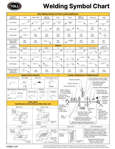
Welding Symbols help welders better understand the types of welds required to manufacture a part. Welding Symbols are often used in engineering drawings by welders and engineers to convey essential information like type of the weld, size of the weld and location of the weld.
Welding Symbol Chart
Basic Welding Symbols and Their Location Significance
| Location Significance | Seam | Back or Backing | Surfacing | Edge |
|---|---|---|---|---|
| Arrow Side |  |  |  |  |
| Other Side |  |  | Not Used |  |
| Both Sides | Not Used | Not Used | Not Used |  |
| No Arrow Side or Other Side Significance |  | Not Used | Not Used | Not Used |
| Location Significance | Fillet | Plug or Slot | Spot or Projection | Stud |
|---|---|---|---|---|
| Arrow Side |  |  |  |  |
| Other Side |  |  |  | Not Used |
| Both Sides |  | Not Used | Not Used | Not Used |
| No Arrow Side or Other Side Significance | Not Used | Not Used |  | Not Used |
| Location Significance | Scarf for Brazed Joint | Groove | ||
|---|---|---|---|---|
| Square | V | Bevel | ||
| Arrow Side |  |  |  |  |
| Other Side |  |  |  |  |
| Both Sides |  |  |  |  |
| No Arrow Side or Other Side Significance | Not Used |  | Not Used | Not Used |
| Location Significance | Groove | |||
|---|---|---|---|---|
| U | J | Flare-V | Flare-Bevel | |
| Arrow Side |  |  |  |  |
| Other Side |  |  |  |  |
| Both Side |  |  |  |  |
| No Arrow Side or Other Side Significance | Not Used | Not Used | Not Used | Not Used |
| Supplementary Symbols | |||
|---|---|---|---|
| Weld-All-Around | Field Weld | Melt-Thru | Consumable Insert |
 |  |  |  |
| Backing/Spacer (Rectangular) | Contour | ||
|---|---|---|---|
 |  |  |  |
| Basic Joints Identification of Arrow Side and Other Side Joint | |
|---|---|
| Butt Joint | Corner Joint |
 |  |
 |  |
 | Where letter designations are to be included in the tail of the welding symbol, reference is made to Table 1, Letter Designations of Welding and Allied Processes and Their Variations, of AWS A2.4-98. American Welding Society 550 N.W. Lejeune Road Miami, Florida 33126 |
| Location of Elements of a Welding Symbol |
|---|
 |
The tail of the symbol is used for designating the welding and cutting processes as well as the welding specifications, procedures, or the supplementary information to be used in making the weld. If a welder knows the size and type of weld, he has only part of the information necessary for making the weld. The process, identification of filler metal that is to be used, whether or not peening or root chipping is required, and other pertinent data must be related to the welder. The notation to be placed in the tail of the symbol indicating these data is to be establish by each user. If notations are not used, the tail of the symbol may be omitted.
Download a Welding Symbol Chart

Need a download as a PDF to print, share, or post for your welding team? Download the welding symbol chart here.
Frequently Asked Questions
Weld symbols are how the designer of a custom metal form communicates how objects should be welded to welders working the manufacturing line. Without clearly-marked weld symbols, the welder won’t know where to place a weld, what type of weld should be made, and the weld size.
The weld symbol distinguishes between the two sides of a joint by using the arrow and the spaces above and below the reference line. The side of the joint to which the arrow points is known as the arrow side, and its weld is made according to the instructions given below the reference line. A welding symbol has three parts:
- Reference line: this is the main part of the symbol and the primary function is to carry or provide all the information on the weld to be made.
- Arrow: is used to point the reference line to where you need to weld.
- Tail: This is used to provide additional but important data as wells as information needed to complete the weld. For example it may contain information on what welding process is to be used, or something else of equal
The main job of symbols is to convey to the welder where to weld, the joint type, how much filler material or metal is to be used, and how much of it needs to be in or on the joint, on a set of plans. Welding symbols are the set of symbols that simplifies communication between the planner and the welders.
The assembled “welding symbol” consists of the following eight elements or any of these elements as necessary:
- Reference line
- Arrow
- Basic weld symbols
- Dimensions and other data
- Supplementary symbols
- Finish symbols
- Tail
- Specification
- Process, or other references